Raspberry Pi
Eurotech provides Raspberry Pi OS-compatible ESF installers (32 and 64-bit) via generic profiles. These can be used as a prototyping platform for testing and evaluation purposes and are not officially supported. Therefore these profiles are not tailored for production.
Ethernet Configuration
The default configuration of the Ethernet interfaces for the Raspberry Pi is the following:
| Interface Name | Gateway Label | Status |
|---|---|---|
| eth0 | N/A | Enabled for WAN - DHCP Client |
Consistent naming of multiple interfaces through adapterIt is possible to connect multiple ethernet interfaces to the device through USB adapters. However, the Raspberry Pi does not follow the consistent interface naming convention out-of-the-box. To enable that feature use the
raspi-configtool and navigate toAdvanced Options / Network Interface Namesmenu.
Wireless Configuration
The wireless interface of the Raspberry Pi is the wlan0. By default, the interface is disabled, keep this in mind when installing ESF via Wi-Fi: the installation can be completed via Wi-Fi but, at the following reboot, ESF will disable as default policy the WI-Fi interface. It can be later re-enabled via the ESF administration web UI.
To set the right Wi-Fi regulatory domain based on your current world region following the instructions here. In case of problems, you could try to edit the /etc/default/crda adding the ISO 3166-1 alpha-2 code of your region.
WLAN Softblock
On Raspbian, it could happen that ‘wlan’ interface is “soft blocked” by default and needs to be enabled. To see if it is blocked run:
rfkill listand unblock it with:
sudo rfkill unblock wlanFirewall Configuration
The default ESF firewall configuration for the the Raspberry Pi is as follows:
| Port | Protocol | Permitted Network | Permitted Interface Name |
|---|---|---|---|
| 67 | udp | 0.0.0.0/0 | eth0 |
| 67 | udp | 0.0.0.0/0 | wlan0 |
| 53 | udp | 0.0.0.0/0 | eth0 |
| 53 | udp | 0.0.0.0/0 | wlan0 |
| 443 | tcp | 10.234.0.0/16 | tun0 |
| 443 | tcp | 0.0.0.0/0 | eth0 |
| 4443 | tcp | 10.234.0.0/16 | tun0 |
| 4443 | tcp | 0.0.0.0/0 | eth0 |
| 22 | tcp | 10.234.0.0/16 | tun0 |
| 22 | tcp | 0.0.0.0/0 | eth0 |
Clock Service
NTS is supported via chrony-advanced option only with chrony version greater then 4.x installed.
GPIO
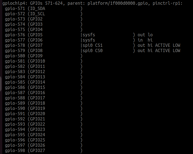
To correctly use the GPIO pins, the user needs to update the jdk.dio.properties file with the proper configuration, based on its own device.
This is required since the sysfs interface has been deprecated, and some OS distribution may have already suppressed it. Moreover, the kernel complains if a static base number is assigned to a GPIO controller: indeed, when it assigns the numbers automatically, it usually starts from 511. More information can be found here.
In order to set the correct configuration the user can perform the following steps:
- On the device run the command
cat /sys/kernel/debug/gpio, looking for entries similar togpio-ABC (GPIxx): from this information it is possible to retrieve which number the GPIO controller was assigned to by the OS (in this case the GPIO controller numberxxis assigned with the numberABC). The image below represent an example of this file

- Modify the
/opt/eclipse/kura/framework/jdk.dio.propertieswith the number and controllers found in the previous step:
573 = deviceType: gpio.GPIOPin, pinNumber:573, name:GPI02
574 = deviceType: gpio.GPIOPin, pinNumber:574, name:GPIO3
575 = deviceType: gpio.GPIOPin, pinNumber:575, name:GPIO4
576 = deviceType: gpio.GPIOPin, pinNumber:576, name:GPIO5
577 = deviceType: gpio.GPIOPin, pinNumber:577, name:GPIO6
578 = deviceType: gpio.GPIOPin, pinNumber:578, name:GPIO7
579 = deviceType: gpio.GPIOPin, pinNumber:579, name:GPIO8
580 = deviceType: gpio.GPIOPin, pinNumber:580, name:GPIO9
581 = deviceType: gpio.GPIOPin, pinNumber:581, name:GPIO10
582 = deviceType: gpio.GPIOPin, pinNumber:582, name:GPIO11
583 = deviceType: gpio.GPIOPin, pinNumber:583, name:GPIO12
584 = deviceType: gpio.GPIOPin, pinNumber:584, name:GPIO13
585 = deviceType: gpio.GPIOPin, pinNumber:585, name:GPIO14
586 = deviceType: gpio.GPIOPin, pinNumber:586, name:GPIO15
587 = deviceType: gpio.GPIOPin, pinNumber:587, name:GPIO16
588 = deviceType: gpio.GPIOPin, pinNumber:588, name:GPIO17
589 = deviceType: gpio.GPIOPin, pinNumber:589, name:GPIO18
590 = deviceType: gpio.GPIOPin, pinNumber:590, name:GPIO19
591 = deviceType: gpio.GPIOPin, pinNumber:591, name:GPIO20
592 = deviceType: gpio.GPIOPin, pinNumber:592, name:GPIO21
593 = deviceType: gpio.GPIOPin, pinNumber:593, name:GPIO22
594 = deviceType: gpio.GPIOPin, pinNumber:594, name:GPIO23
595 = deviceType: gpio.GPIOPin, pinNumber:595, name:GPIO24
596 = deviceType: gpio.GPIOPin, pinNumber:596, name:GPIO25
597 = deviceType: gpio.GPIOPin, pinNumber:597, name:GPIO26
598 = deviceType: gpio.GPIOPin, pinNumber:598, name:GPIO27

gpio.GPIOPin = initValue:0, deviceNumber:0, direction:3, mode:-1, trigger:3
uart.UART = baudRate:19200, parity:0, dataBits:8, stopBits:1, flowControl:0
You can also check your GPIO device configuration executing the command pinout if available on your system.
Updated 3 months ago
