GPIO Driver Application
In this section a simple but effective example about the ESF GPIO Driver on Wires will be presented. The examples use a ReliaGATE 10-11 or 10-12.
Read unsolicited data from a GPIO
This example will implement a Wire graph that toggles a digital GPIO. A listener will be attached to an input GPIO externally connected to the first one.
Using a ReliaGATE 10-11 or 10-12, connect together the CAN1 GND pin, the Digital IN 1C pin and the Digital OUT 1NO pin. Then connect together the CAN1 5V pin with the Digital OUT 1COM pin. Finally connect the Digital OUT 1COM with Digital IN 1A pin. In this way, we connect an output GPIO (Digital OUT 1) with an input one (Digital IN 1).
Following the procedure presented in the previous section, create 3 Assets linked to the GPIO Driver:
- CAN1Asset: it is used only to enable the CAN1 power supply and power the CAN1 5V pin. Configure it as shown in the following picture, select the Data tab and write true in to the Value form. Then apply.

- GPIOAsset: it toggles the DOUT1 digital output. Configure as follows:

- GPIOAssetListener: it is linked to the digital input GPIO. Configure as follows:

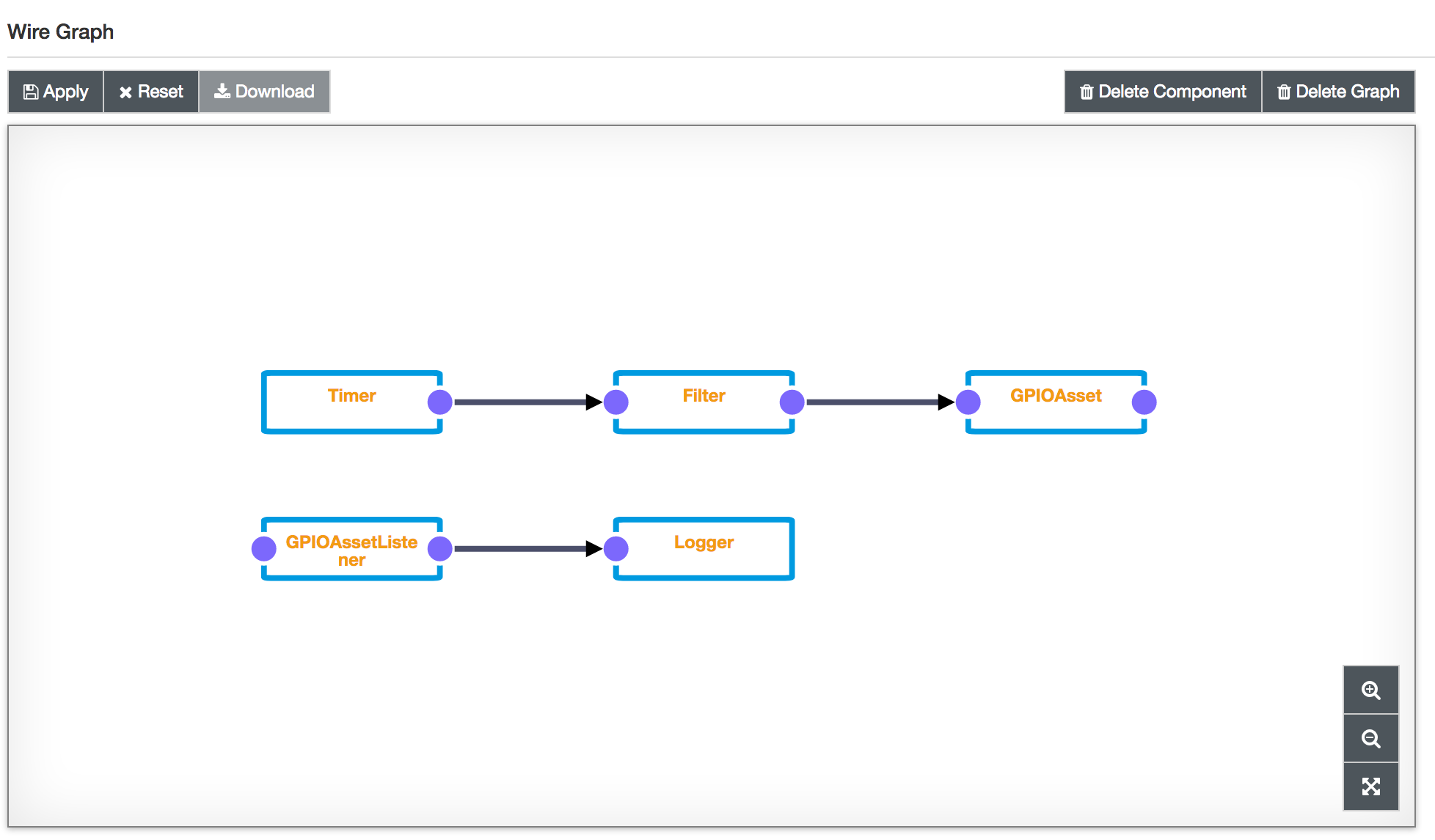
Then create the following Wire graph, where the Filter component is a ScriptFilter whose script is the following:
// create a persistent counter
counter = typeof(counter) === 'undefined' ? 0 : counter
counter++

// emit the counter value in a different WireRecord
var counterRecord = newWireRecord()
counterRecord.DOUT1 = newBooleanValue(counter%2==0)
output.add(counterRecord)
The above script will toggle the DOUT1 GPIO on and off with the period defined by the Timer. Configure the Logger component as Verbose and observe in to the log that every toggle corresponds to a Wire Envelope emitted by the GPIOAssetListener.
Updated 4 months ago
