Modbus to DNP3 conversion example
Simulate a slave using Modbuspal
The first step involves simulating a Modbus TCP slave using the modbuspal simulator. Note: the simulator requires a Java Virtual Machine.
Download and start modbuspal
- Download the ModbusPAL Modbus slave simulator and start it.
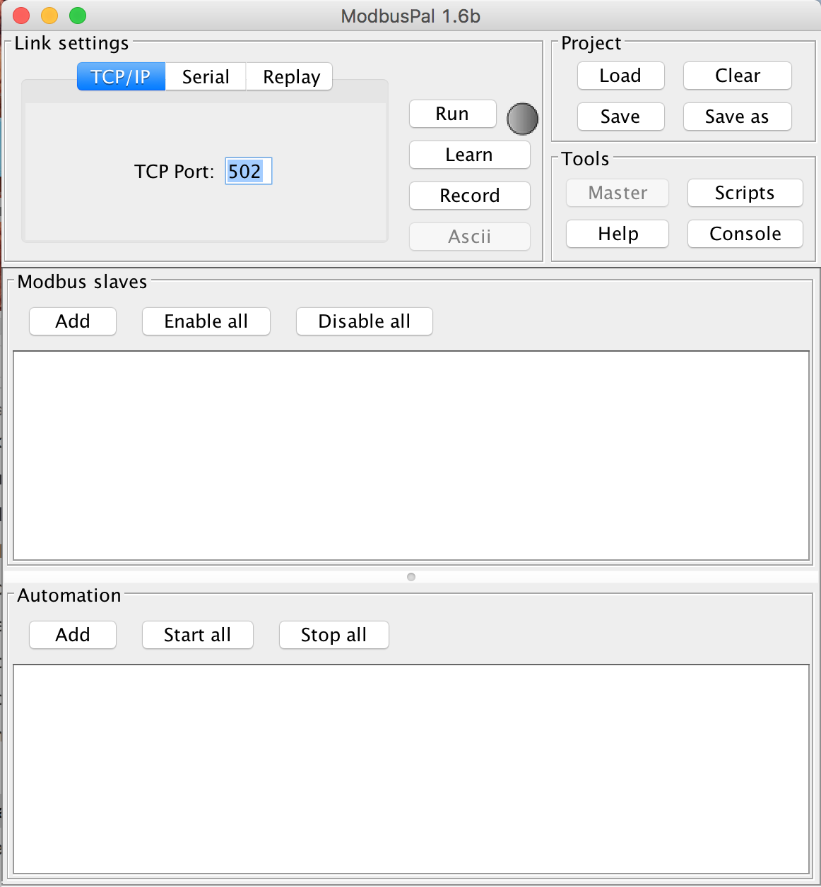
- Change TCP Port to 5020 and make sure that such port is open in the firewall configuration of the machine running ModbusPAL.
Add a new unit
- Press Add under Modbus slaves, select 1 and press Add.
- A new entry should appear reporting
unknown slaveas name
Add some holding registers and coil to the simulated unit
- Click on the eye icon next to
unknown slave, the following dialog should appear.
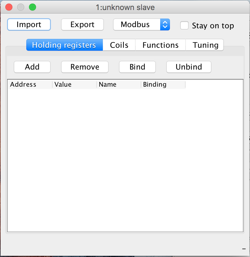
- Select the Holding registers tab, click on Add, and then on Add again in the dialog.
- Select the Coil tab, click on Add, and then on Add again in the dialog.
- Return to the main dialog and click Run
Change some holding register and coil values
- Holding register and coil values can be changed by clicking on the value cell of a table entry and inserting the desired value.
Configure ESF modbus driver to read some data from the simualtor
Install the Modbus Driver
- Access ESF Web UI by opening the
http://<gateway ip>URL with a browser, default username/password are admin/admin. - Navigate to the System -> Packages section.
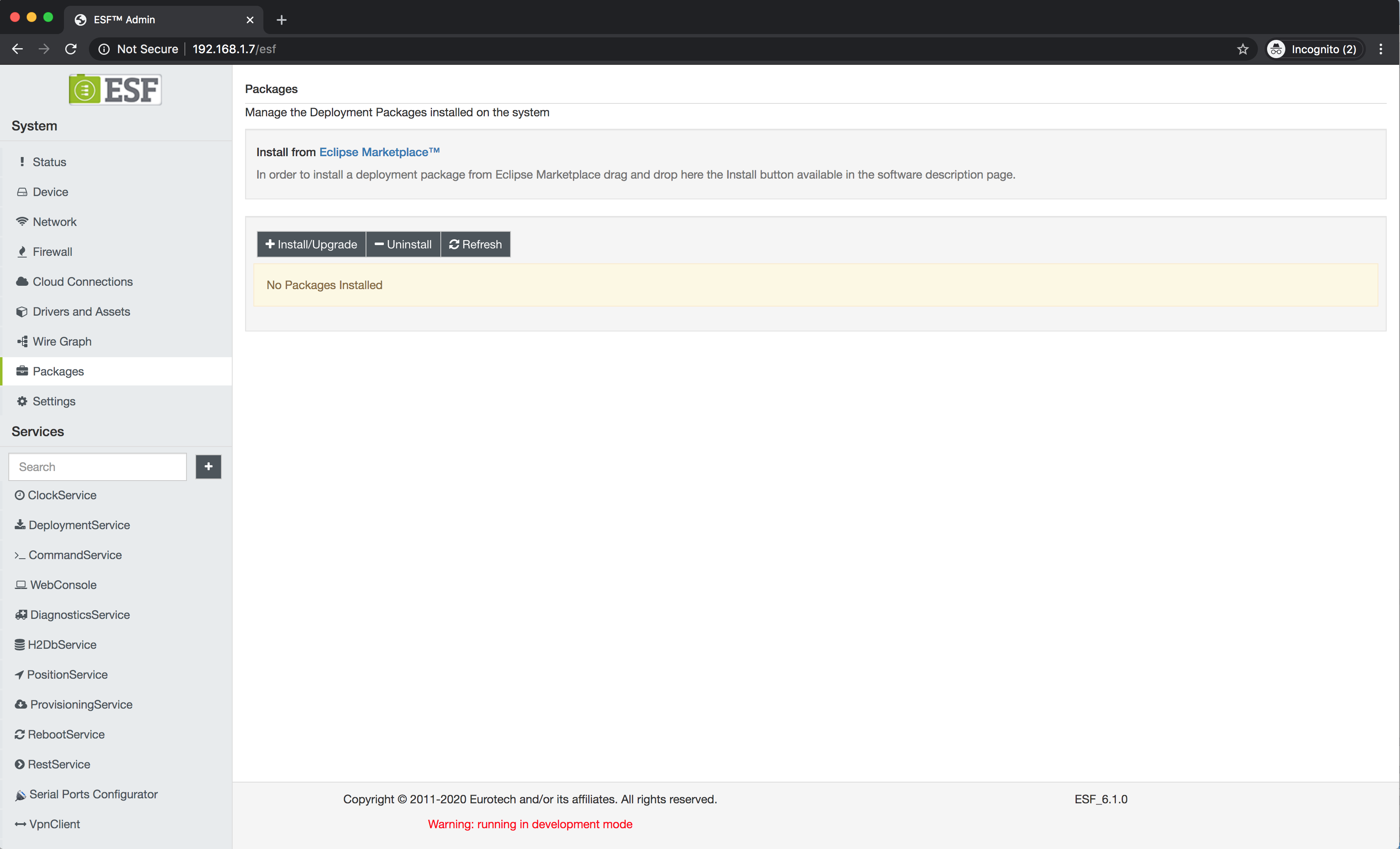
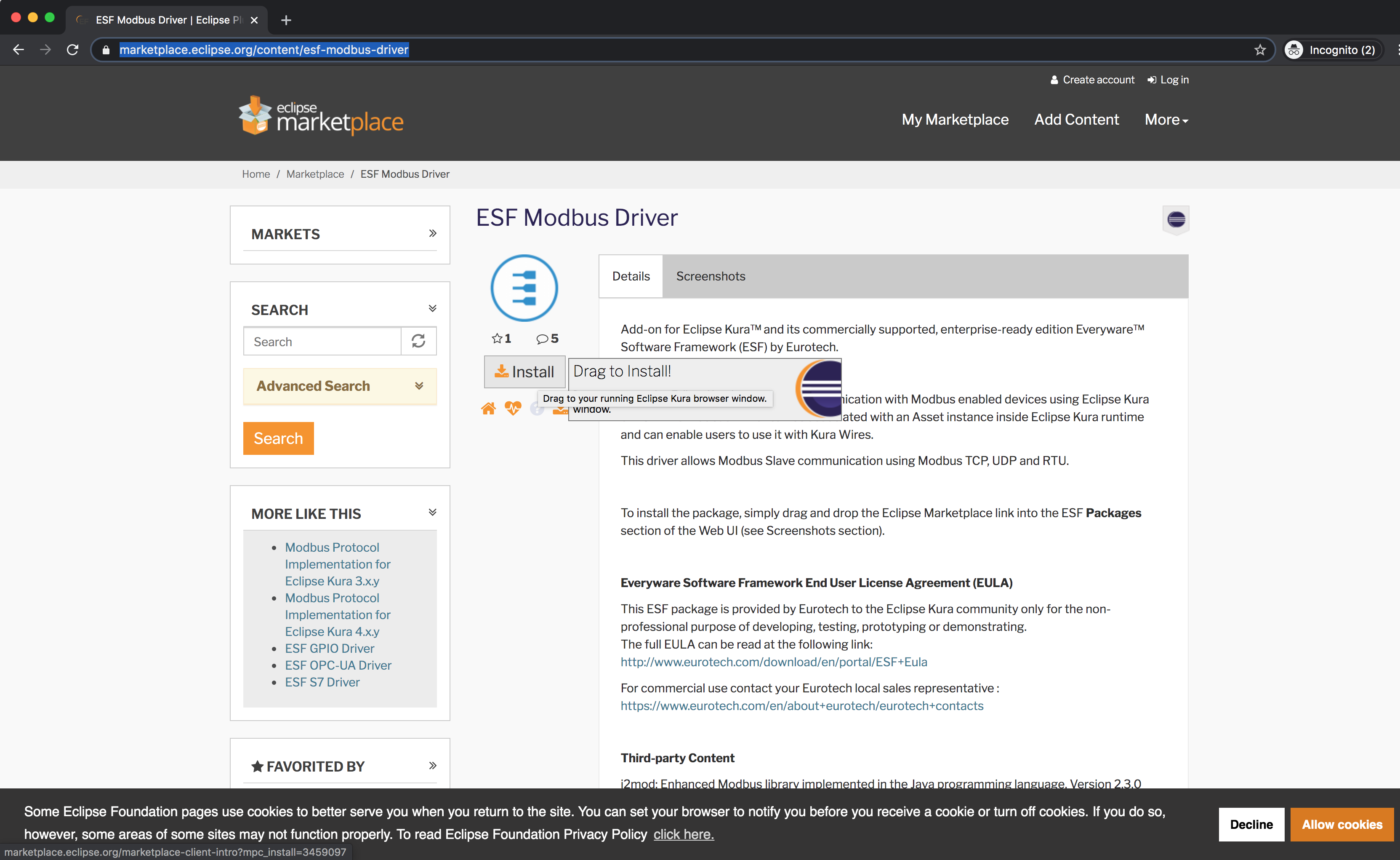
- Open https://marketplace.eclipse.org/content/esf-modbus-driver in a separate browser window.
- Drag and drop the Install button on the packages section of ESF Web UI. (In order to complete this step the gateway must have WAN connectivity).
Create a Modbus Driver instance
- Navigate to the Drivers and Assets section of ESF Web UI.
- Click on the New Driver button.
- Select
org.eclipse.kura.driver.modbusas Driver Factory. - Enter an arbitrary name for the driver instance in the Driver name field, for example
modbusSimulator. - Click on the
modbusSimulatorentry in the table.
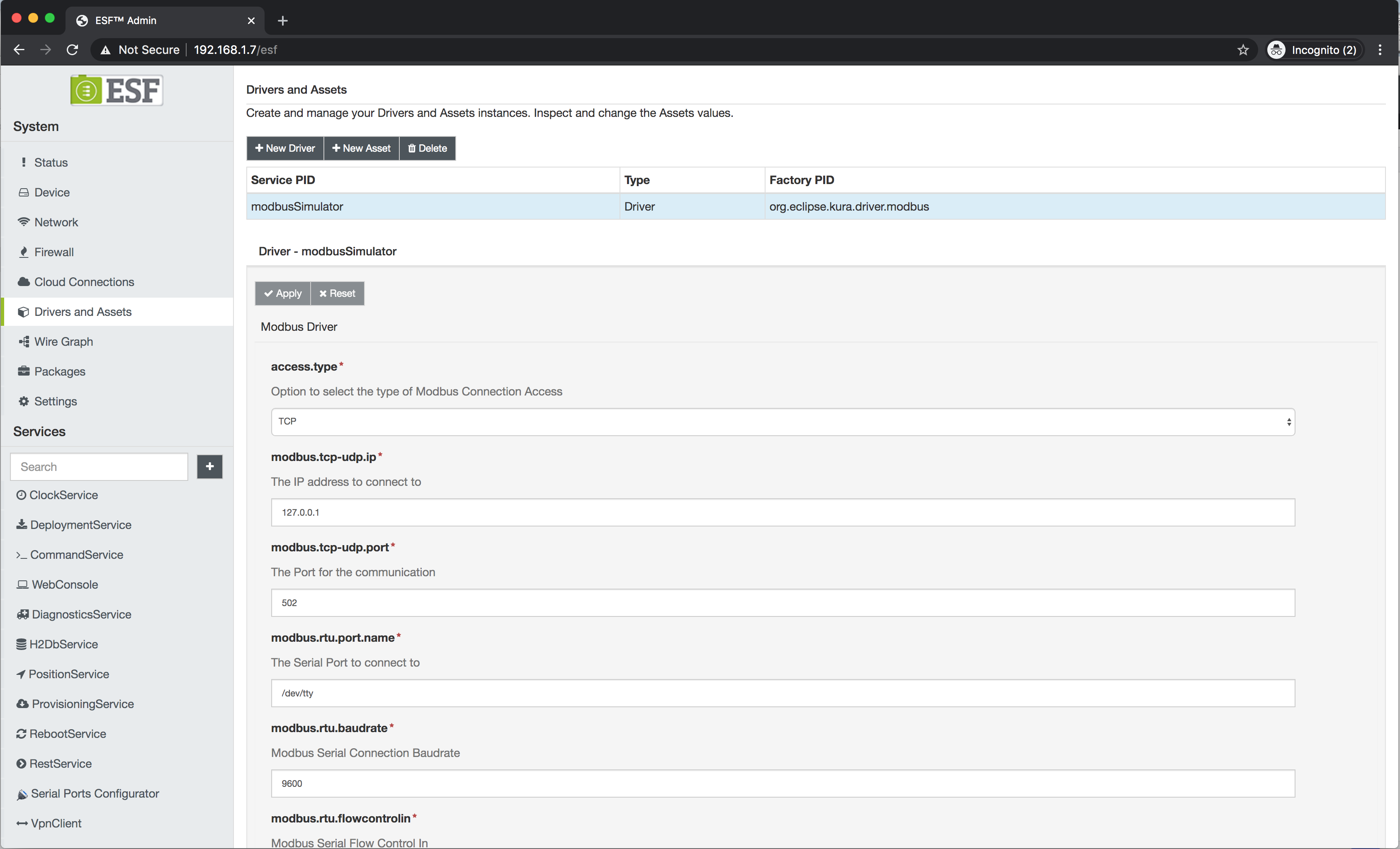
- Set modbus.tcp-udp.ip to the IP address/hostname of the machine running ModbusPAL.
- Set modbus.tcp-udp.port to 5020.
Configure the driver to read some data
- Click on the
modbusSimulatorentry in the table. - Click on the New Asset button.
- Enter an arbitrary name for the asset instance in the Asset Name field, for example
modbusAsset. - Configure the asset as shown in the picture below, this will create an Asset configuration that reads holding registers 1 and 2 and coils 1 and 2.
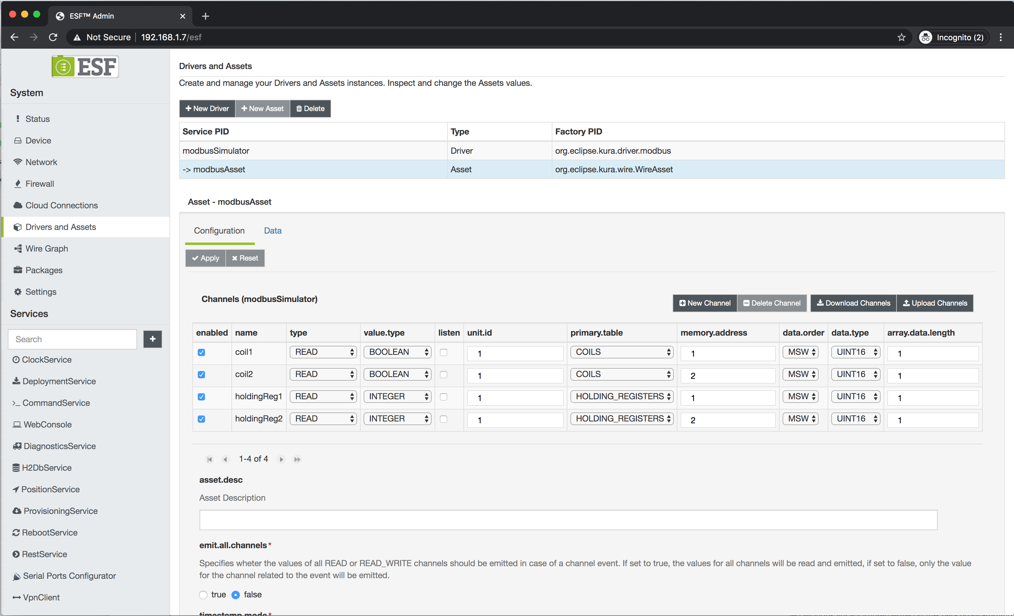
- Click on the Data tab, if the Modbus connection is ok, the current register values should be shown.
Read the values periodically using a Wire Graph
In order to create some logic that periodically reads the values, a simple Wire Graph can be created as follows:
- Navigate to the Wire Graph section of ESF Web UI.
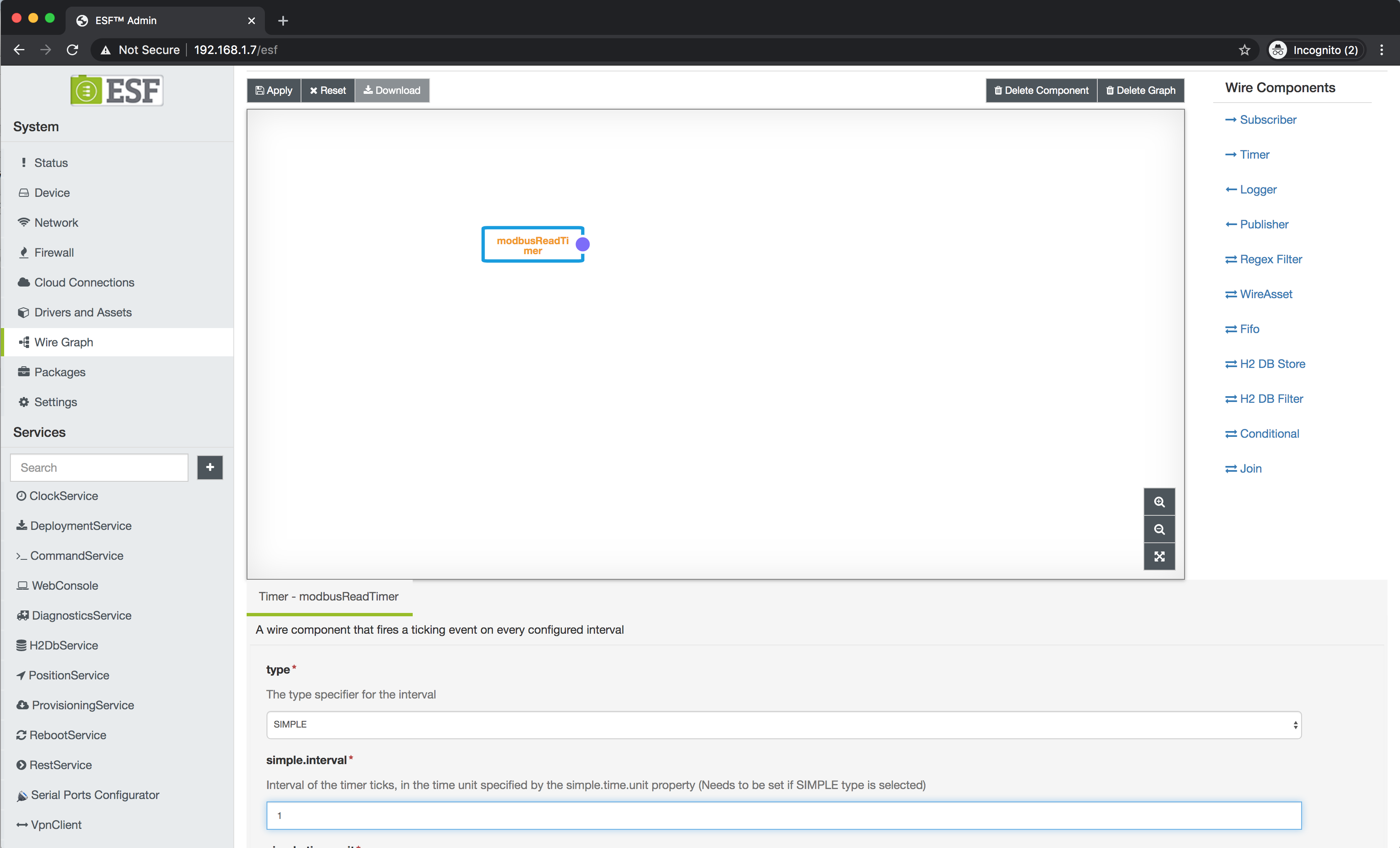
- Drag and Drop a Timer component in the canvas
- Assign an arbitrary name to the timer component, for example
modbusReadTimer, and press OK. - Click on the component
- Enter 1 as simple.interval, this property defines the poll rate.
- Drag a WireAsset component to the canvas.
- Select
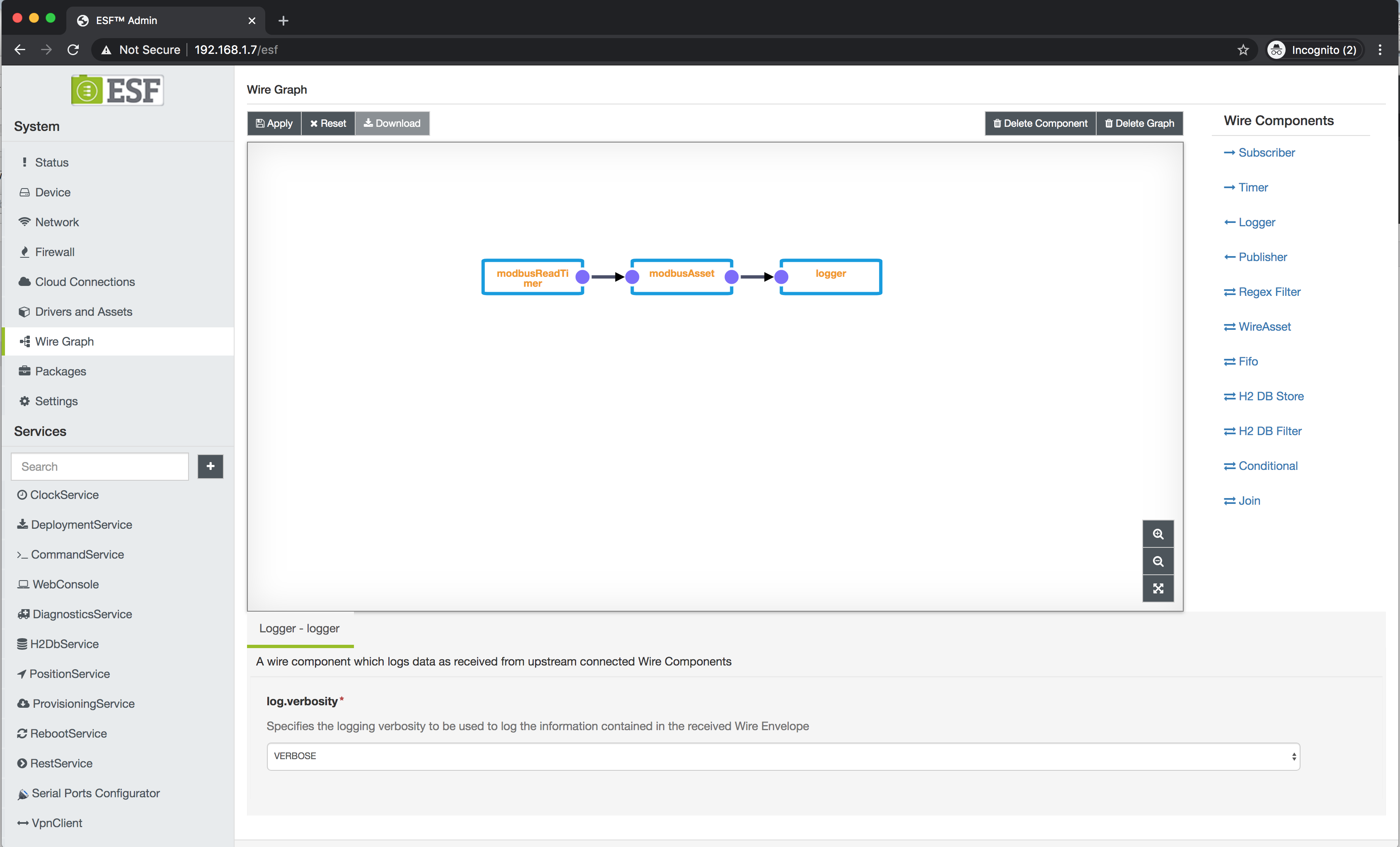
modbusAssetfrom the list and click OK. This will add the asset defined above to the graph. - Drag a Logger component to the canvas and assign a name to it, for example
logger. - Click on the
loggercomponent. - Set log.verbosity to
VERBOSE. The logger component will print the data produced by the asset in device log. - Connect the components as shown in the picture and press Apply.
The logger is useful for inspecting the values emitted by another Wire Component.
The logs can be viewed by opening an SSH connection to the device, for example using the following command in Linux/OSX terminal or Windows 10 PowerShell:
ssh root@<device ip>
The default password is eurotech.
Once the SSH connection is established, ESF logs can be viewed using the following command:
tail -F /var/log/kura.log
Messages like the following should be printed every second:
2020-04-21T11:27:17,346 [DefaultQuartzScheduler_Worker-9] INFO  o.e.k.i.w.l.Logger - Received WireEnvelope from org.eclipse.kura.wire.WireAsset-1587466852771-26
2020-04-21T11:27:17,348 [DefaultQuartzScheduler_Worker-9] INFO  o.e.k.i.w.l.Logger - Record List content:
2020-04-21T11:27:17,350 [DefaultQuartzScheduler_Worker-9] INFO  o.e.k.i.w.l.Logger -   Record content:
2020-04-21T11:27:17,352 [DefaultQuartzScheduler_Worker-9] INFO  o.e.k.i.w.l.Logger -     holdingReg2_timestamp : 1587468437346
2020-04-21T11:27:17,354 [DefaultQuartzScheduler_Worker-9] INFO  o.e.k.i.w.l.Logger -     coil2_timestamp : 1587468437343
2020-04-21T11:27:17,356 [DefaultQuartzScheduler_Worker-9] INFO  o.e.k.i.w.l.Logger -     holdingReg1_timestamp : 1587468437345
2020-04-21T11:27:17,358 [DefaultQuartzScheduler_Worker-9] INFO  o.e.k.i.w.l.Logger -     coil2 : false
2020-04-21T11:27:17,360 [DefaultQuartzScheduler_Worker-9] INFO  o.e.k.i.w.l.Logger -     coil1 : false
2020-04-21T11:27:17,362 [DefaultQuartzScheduler_Worker-9] INFO  o.e.k.i.w.l.Logger -     assetName : modbusAsset
2020-04-21T11:27:17,364 [DefaultQuartzScheduler_Worker-9] INFO  o.e.k.i.w.l.Logger -     holdingReg1 : 0
2020-04-21T11:27:17,366 [DefaultQuartzScheduler_Worker-9] INFO  o.e.k.i.w.l.Logger -     holdingReg2 : 0
2020-04-21T11:27:17,367 [DefaultQuartzScheduler_Worker-9] INFO  o.e.k.i.w.l.Logger -     coil1_timestamp : 1587468437343
2020-04-21T11:27:17,370 [DefaultQuartzScheduler_Worker-9] INFO  o.e.k.i.w.l.Logger -
Install DNP3 slave driver
- Download the com.eurotech.framework.dnp3.slave.driver.armv7hf.feature deployment package.
- Access ESF Web UI by opening the
http://<gateway ip>URL with a browser, default username/password are admin/admin. - Navigate to the System -> Packages section.
- Click on the Install/Upgrade button.
- Select the com.eurotech.framework.dnp3.slave.driver.armv7hf.feature deployment package downloaded before and click on Submit
Create a DNP3 slave driver instance
- Navigate to the Drivers and Assets section of ESF Web UI.
- Click on the New Driver button.
- Select
com.eurotech.framework.internal.dnp3.slave.driver.Dnp3SlaveDriveras Driver Factory. - Enter an arbitrary name for the driver instance in the Driver name field, for example
dnp3Slave.
With the default configuration, the slave will listen on port 20000 and use 1024 as link layer address.
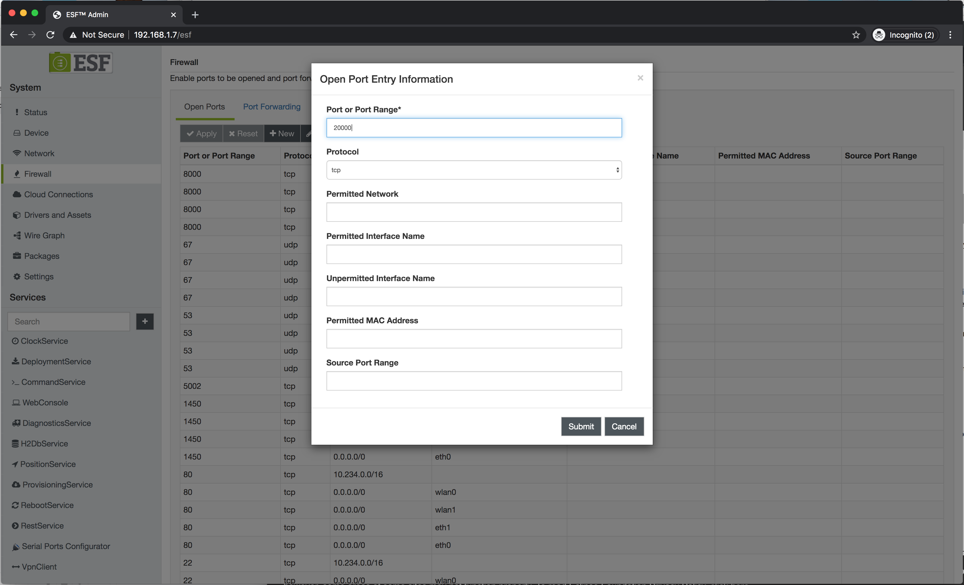
Open port 20000 in device firewall
- Navigate to the Firewall section of ESF Web UI.
- Click on the New button.
- Enter 20000 as Port or Port Range and click Submit
- Click Apply
Define a mapping for the Modbus values
A simple mapping between the data that the Modbus driver is currently configured to read and DNP3 data points can be the following:
- Modbus Holding Register 1 <-> DNP3 Analog Input 0
- Modbus Holding Register 2 <-> DNP3 Analog Input 1
- Modbus Coil 1 <-> DNP3 Binary Input 0
- Modbus Coil 2 <-> DNP3 Binary Input 1
The mapping can be defined by creating a DNP3 slave driver Asset with suitable channels, and configuring the Wire Graph to write the data coming from Modbus asset into DNP3 asset.
Define a DNP3 asset for input values
- Navigate to the Drivers and Assets section of ESF Web UI.
- Click on the
dnp3Slaveentry in the table. - Click on the New Asset button.
- Enter an arbitrary name for the asset instance in the Asset Name field, for example
dnp3Input. - Configure the asset as shown in the picture below.
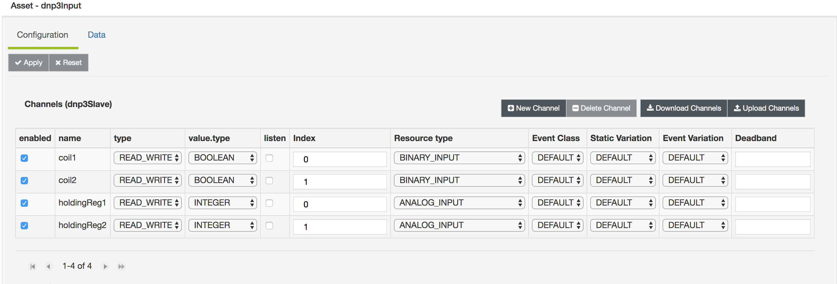
The following rules are important for the mapping:
- All DNP3 slave driver asset channels must use
READ_WRITEas type. - The values of the name and value.type properties of DNP3 slave driver channels must exactly match the corresponding values of Modbus asset channels.
Configure the Wire Graph to perform the mapping
At this point the DNP3 Asset is configured but no component is updating its values yet.
- Navigate to the Wire Graph section of ESF Web UI.
- Drag and drop a WireAsset component to the canvas.
- Select
dnp3Inputfrom the list and click OK. - Connect
modbusAssettodnp3Input
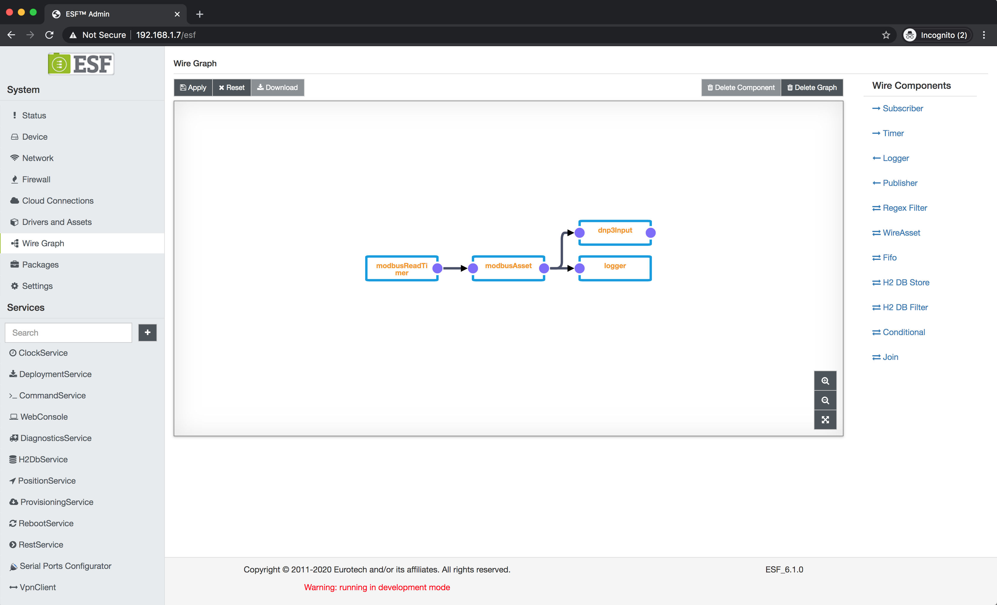
At this point, every time the timer ticks, the values are read from the Modbus asset and written into the DNP3 asset. If should be possible to retrieve the values by connecting a DNP3 master to the device. With default DNP3 driver configuration, changes in modbus values should be reported with unsolicited messages as well.
The following details about Wires, Assets and their interaction are important to understand how the mapping works:
Wires
- A message flowing in the graph is called
WireEnvelope. - Each
WireEnvelopecontains a list ofWireRecords. - Each
WireRecordcontains a set of key-value pairs, called properties.- The property key is a string
- The property value can have one of the following types
- BOOLEAN
- BYTE_ARRAY
- DOUBLE
- INTEGER
- LONG
- FLOAT
- STRING
WireAsset
- Every time a WireAsset receives an envelope on its input port, it will read the values of all of its channels with
READorREAD_WRITEtype.
- The result is emitted as a
WireEnvelopewith a singleWireRecord - The
WireRecordcontains the following properties:- a property with key
assetName, value typeSTRINGand the emitting asset asset name as value
For each channel in asset configuration withREADorREAD_WRITEtype named<channel name>: - a property with key =
<channel name>, value type = value.type in channel configuration and value = value obtained from read operation. This property will be present only if the read operation is successful. - a property with key =
<channel name>_timestampvalue type =LONGreporting a timestamp in milliseconds since UNIX epoch. This property will be present only if the timestamp.mode Asset configuration property isPER_CHANNEL - a property with key =
<channel name>_errorvalue type =STRINGreporting an error message. This property will be present only if read operation fails and the emit.errors Asset configuration property is set totrue.
- a property with key
The structure above can be seen in logger output. Read operation is performed regardless of input record content.
Additionally, the Wire Graph can also be used to update asset values through write operations, according to the following rule.
- Every time a WireAsset receives an envelope on its input port, for each property contained in the received
WireRecords with key<key>, value type<value type>and value<value>:
- If a channel with name
<key>is defined in asset configuration whose value.type is equal to<value type>, then the Asset will write<value>to the channel.
In the setup constructed so far, the Timer emits an envelope every second, triggering a read from the Modbus asset due to rule 1. The envelope emitted by the Modbus Asset will trigger a write on the DNP3 slave Asset updating the values, due to rule 2.
It is also possible to use other wire components to update the values in DNP3 Asset (for example the ScriptFilter), as long as rule 2. is respected.
### Updating modbus register values
It is also possible to use DNP3 commands to update Modbus register values.
In order to do this, another pair of assets must be created.
Create a DNP3 output asset
- Navigate to the Drivers and Assets section of ESF Web UI.
- Click on the
dnp3Slaveentry in the table. - Click on the New Asset button.
- Enter an arbitrary name for the asset instance in the Asset Name field, for example
dnp3Output. - Configure the asset as shown in the picture below.
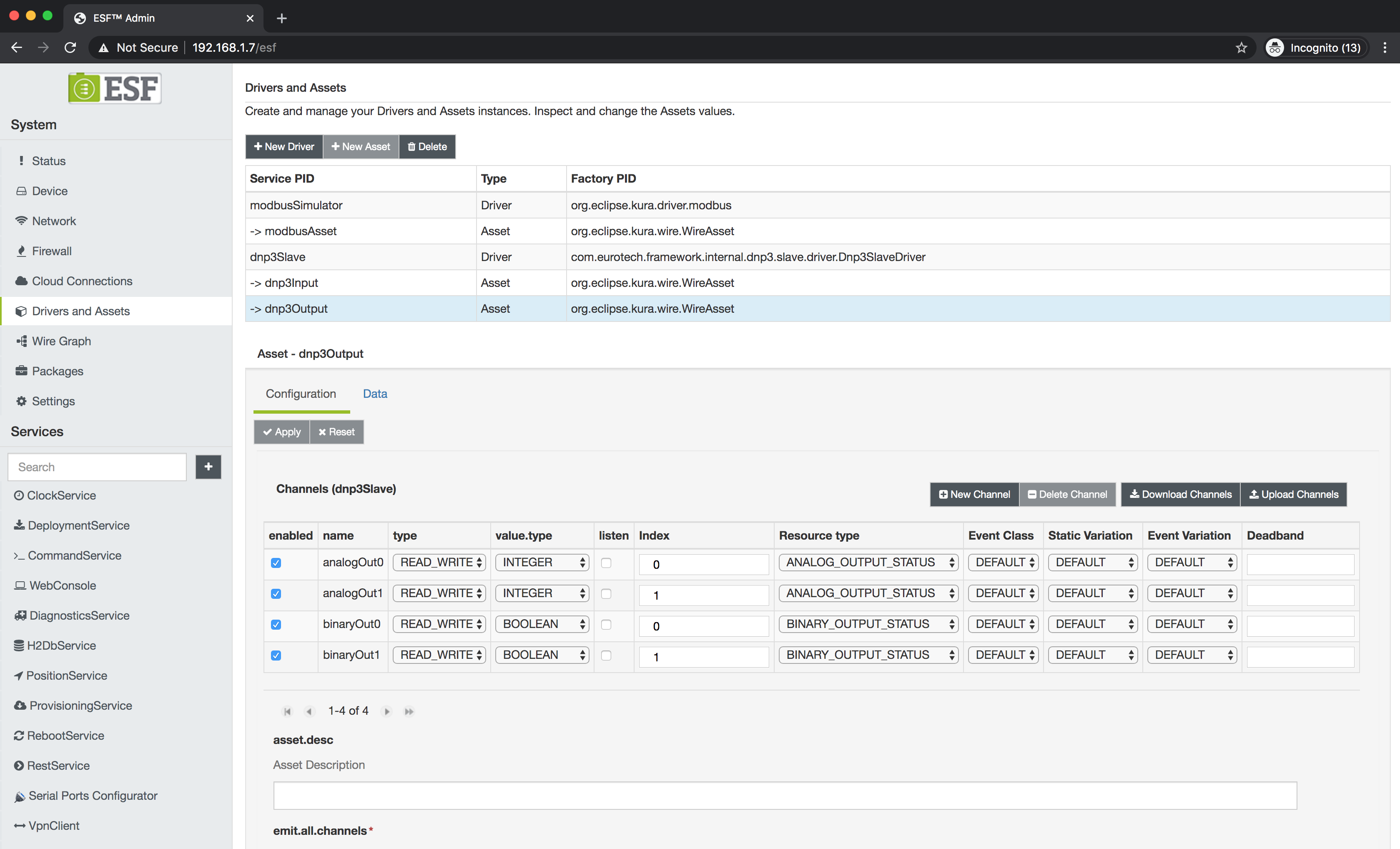
Sending CROB or analog output commands to the gateway will have the effect of changing the value of corresponding data points. The received values can be retrieved using the Wire Graph.
In case of CROB commands, the control codes that set binary output status value to the on and off state can be defined in global driver configuration.
Create a test graph for the output asset
- Navigate to the Wire Graph section of ESF Web UI.
- Drag and Drop a Timer component in the canvas
- Assign an arbitrary name to the timer component, for example
modbusWriteTimer, and press OK. - Click on the component
- Enter 1 as simple.interval.
- Drag a WireAsset component to the canvas.
- Select
dnp3Outputfrom the list and click OK. This will add the asset defined above to the graph. - Connect the components as shown in the picture and press Apply.
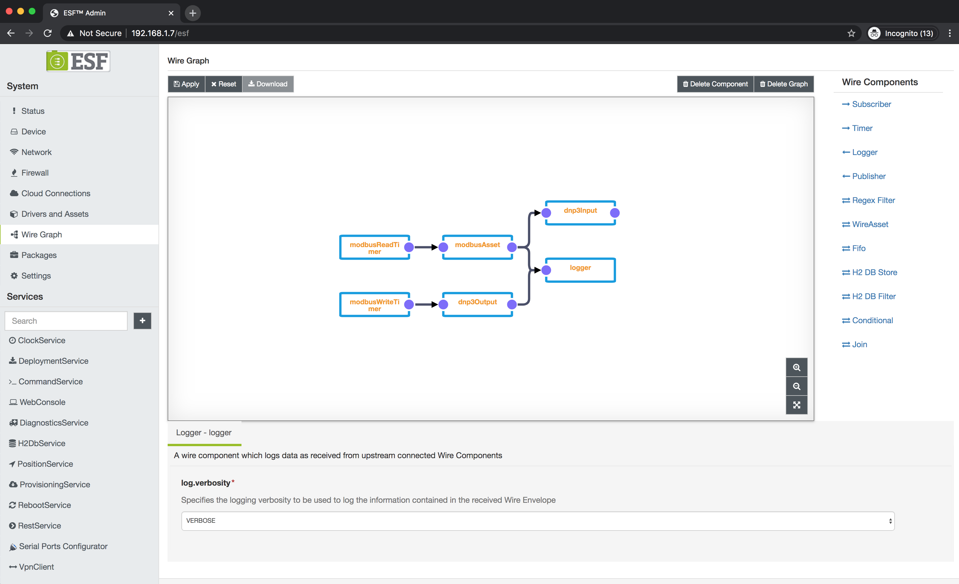
Sending commands from a DNP3 master for index 0 and 1 should cause the received values to be printed on the log every second.
#### Create a Modbus asset for writing output registers
- Click on the
modbusSimulatorentry in the table. - Click on the New Asset button.
- Enter an arbitrary name for the asset instance in the Asset Name field, for example
modbusWrite. - Configure the asset as shown in the picture below, this will create an Asset configuration that writes to holding registers 10 and 11 and coils 10 and 11.
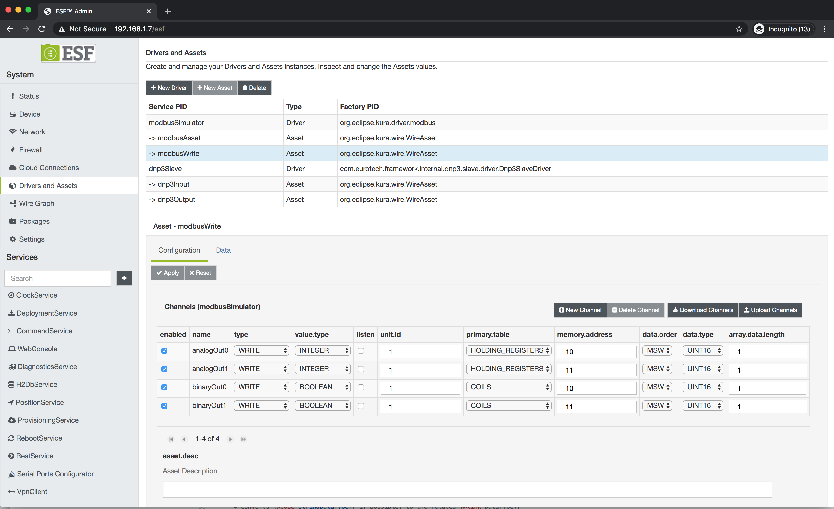
The modbus asset above will implement the following mapping
- DNP3 Analog Output Status 0 <-> Modbus Holding Register 10
- DNP3 Analog Output Status 1 <-> Modbus Holding Register 11
- DNP3 Binary Output Status 0 <-> Modbus Coil 10
- DNP3 Binary Output Status 1 <-> Modbus Coil 11
#### Add the Modbus write asset to the Wire Graph
- Navigate to the Wire Graph section of ESF Web UI.
- Drag and drop a WireAsset component to the canvas.
- Select
modbusWritefrom the list and click OK. - Connect
dnp3OutputtomodbusWrite
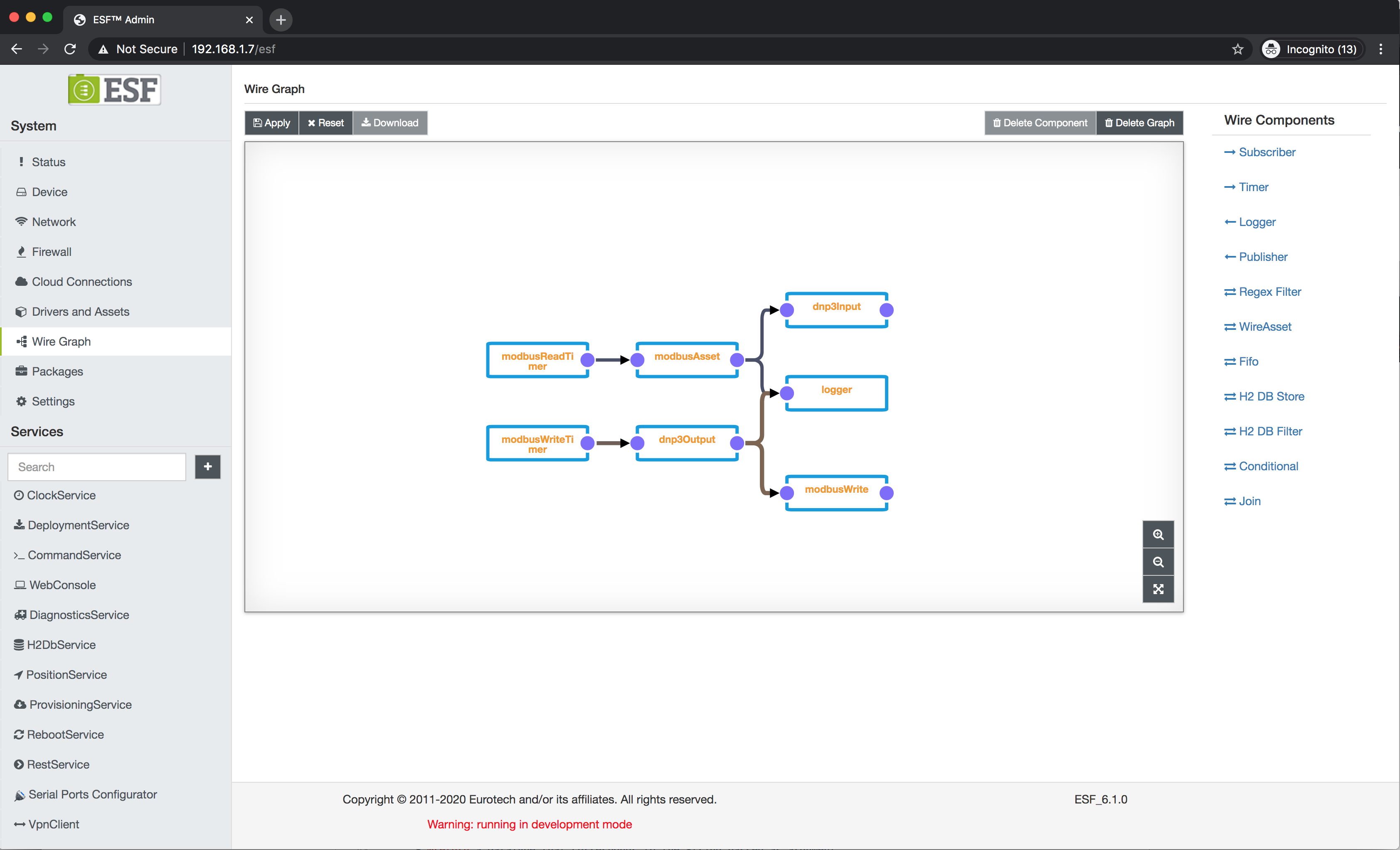
The values sent by the DNP3 master will now be written to the modbus slave every second.
The output mapping works due to the same rules that apply for the read branch.
Using listen mode
DNP3 Assets support emitting WireEnvelopes spontaneously when a command is received, this allows to remove the modbusWriteTimer component and perform write operations to Modbus only on event.
- Navigate to the Wire Graph section of ESF Web UI.
- Delete the
modbusWriteTimercomponent. - Select the
dnp3Outputcomponent. - Tick the listen flag on all channels
- Click Apply
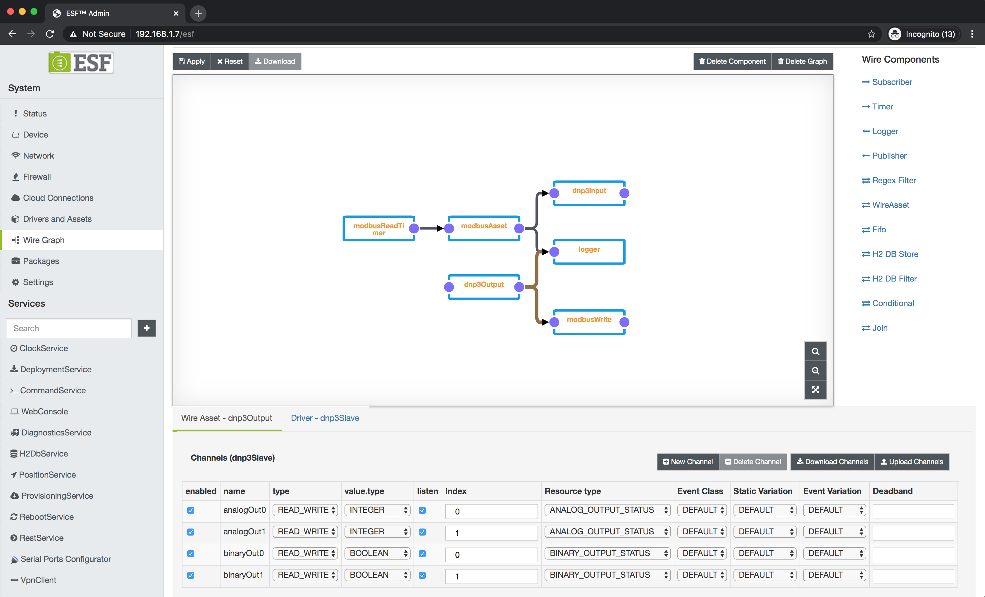
Updated 3 months ago
